Element 3 Question 3-32D4
C3D32: Schematics
In Figure 3D9, determine if there is a problem with this regulated power supply and identify the problem.
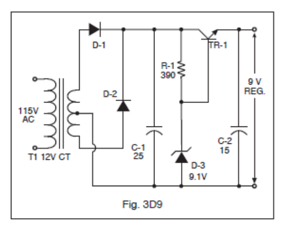
- R1 value is too low which would cause excessive base current and instantly destroy TR 1.
- D1 and D2 are reversed. The power supply simply would not function.
- TR1 is shown as an NPN and must be changed to a PNP.
- There is no problem with the circuit. (correct answer)
Correct answer: D, There is no problem with the circuit.
Explanation
D-1 and D-2 form a center-tapped full-wave rectifier with both cathodes on the + line, and C-1 filters the result. R-1 feeds the 9.1 V zener D-3, which holds TR-1's base at a steady voltage. TR-1 is an NPN emitter follower used as the series pass transistor, so the output is one base-emitter drop below the zener: 9.1 V − 0.6 V ≈ 8.5 V (marked 9 V). C-2 bypasses the output. Every part is oriented correctly.
Why the other answers are wrong
- A, R1 value is too low which would cause excessive base current and instantly destroy TR 1.: 390 Ω is a normal zener feed resistor. It passes a modest bias current of roughly 20 mA or less, shared by D-3 and TR-1's base, which is far too little to destroy the transistor.
- B, D1 and D2 are reversed. The power supply simply would not function.: Both diode cathodes face the + line, which is correct for a positive-output full-wave rectifier. Reversing them would make the output negative.
- C, TR1 is shown as an NPN and must be changed to a PNP.: An NPN emitter follower with its collector on the positive unregulated line is the standard series pass transistor for a positive supply. A PNP would be wrong here.