Element 3 Question 3-50F5
C3F50: Receiver Performance
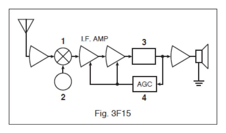
In Figure 3F15 (EL3-D1) at what point in the circuit (labeled 1 through 4) could a DC voltmeter be used to monitor signal strength?
- 1
- 2
- 3
- 4 (correct answer)
Correct answer: D, 4
Explanation
The AGC circuit at 4 turns the detector output into a DC control voltage that rises and falls with the strength of the received signal. It feeds that voltage back to reduce IF gain on strong signals. Because this voltage follows signal strength, a DC voltmeter connected there acts as a signal-strength (S) meter. The other points carry RF, IF or audio, which a DC meter cannot usefully read.
Why the other answers are wrong
- A, 1: Point 1 is the mixer, which carries RF and IF signals. There is no steady DC level there that follows signal strength.
- B, 2: Point 2 is the local oscillator. Its output stays the same whatever the incoming signal strength, so it tells you nothing about received signal level.
- C, 3: Point 3 is the detector, whose main output is audio. The smoothed DC level that tracks signal strength is taken off in the AGC at 4.