General Question G7A09
G7A: Power supplies; schematic symbols
Which symbol in figure G7-1 represents a field effect transistor?
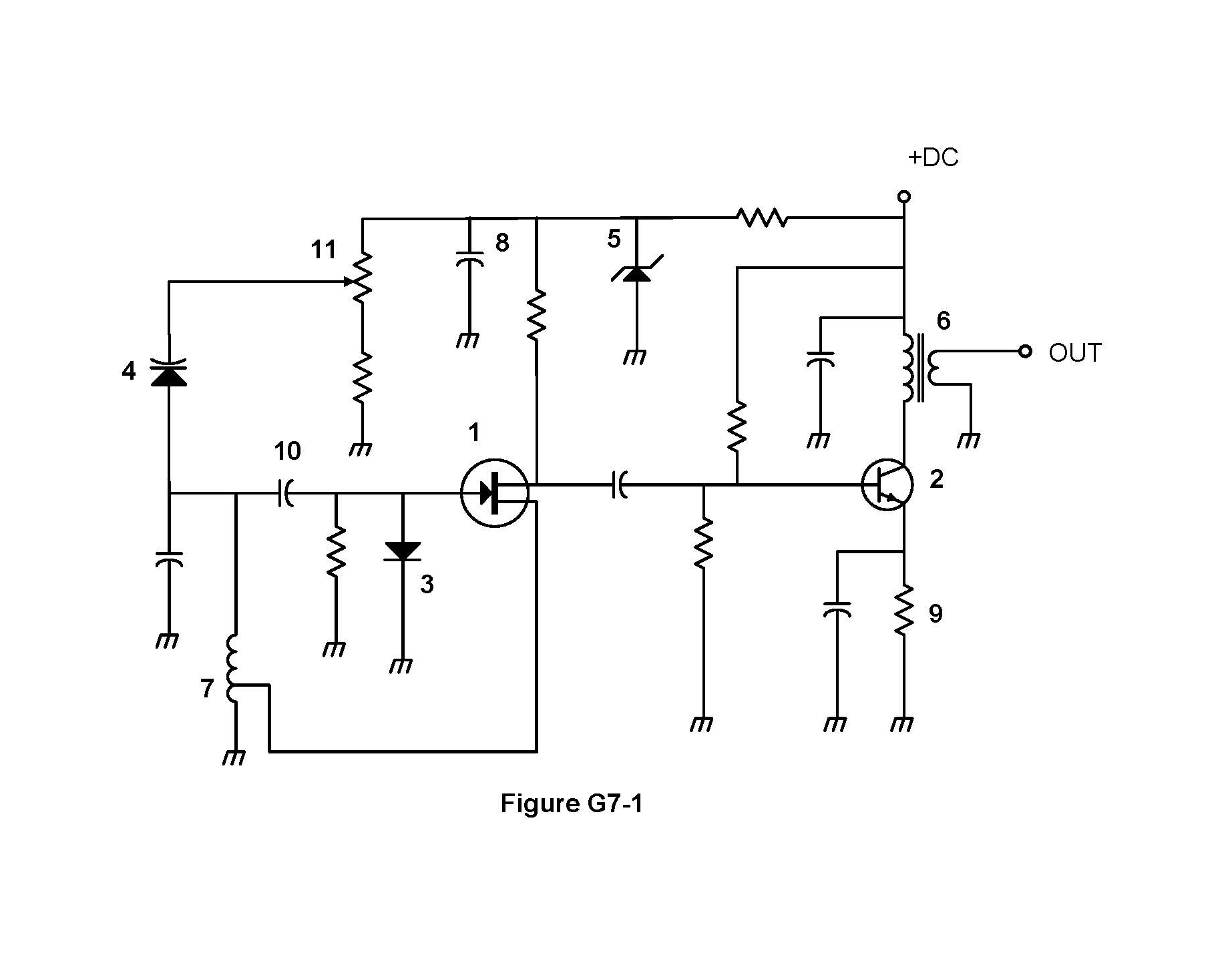
- Symbol 2
- Symbol 5
- Symbol 1 (correct answer)
- Symbol 4
Correct answer: C, Symbol 1
Explanation
Symbol 1 is a junction field effect transistor (JFET). A circle surrounds a vertical bar for the channel, with drain and source leads on one side. The gate lead enters from the other side with an arrow pointing in, which marks an N-channel device. A bipolar transistor looks different: its base meets a short bar, and its collector and emitter leads slant off at an angle.
Why the other answers are wrong
- A, Symbol 2: Symbol 2 is an NPN bipolar junction transistor. Its slanted emitter lead carries an arrow pointing outward, not the straight gate of a FET.
- B, Symbol 5: Symbol 5 is a Zener diode, a diode symbol whose bar has bent ends. Here it holds the supply voltage steady.
- D, Symbol 4: Symbol 4 is a varactor, a diode with a capacitor plate drawn beside it. It works as a voltage-controlled capacitor for tuning.