General Question G7A13
G7A: Power supplies; schematic symbols
Which symbol in Figure G7-1 represents a tapped inductor?
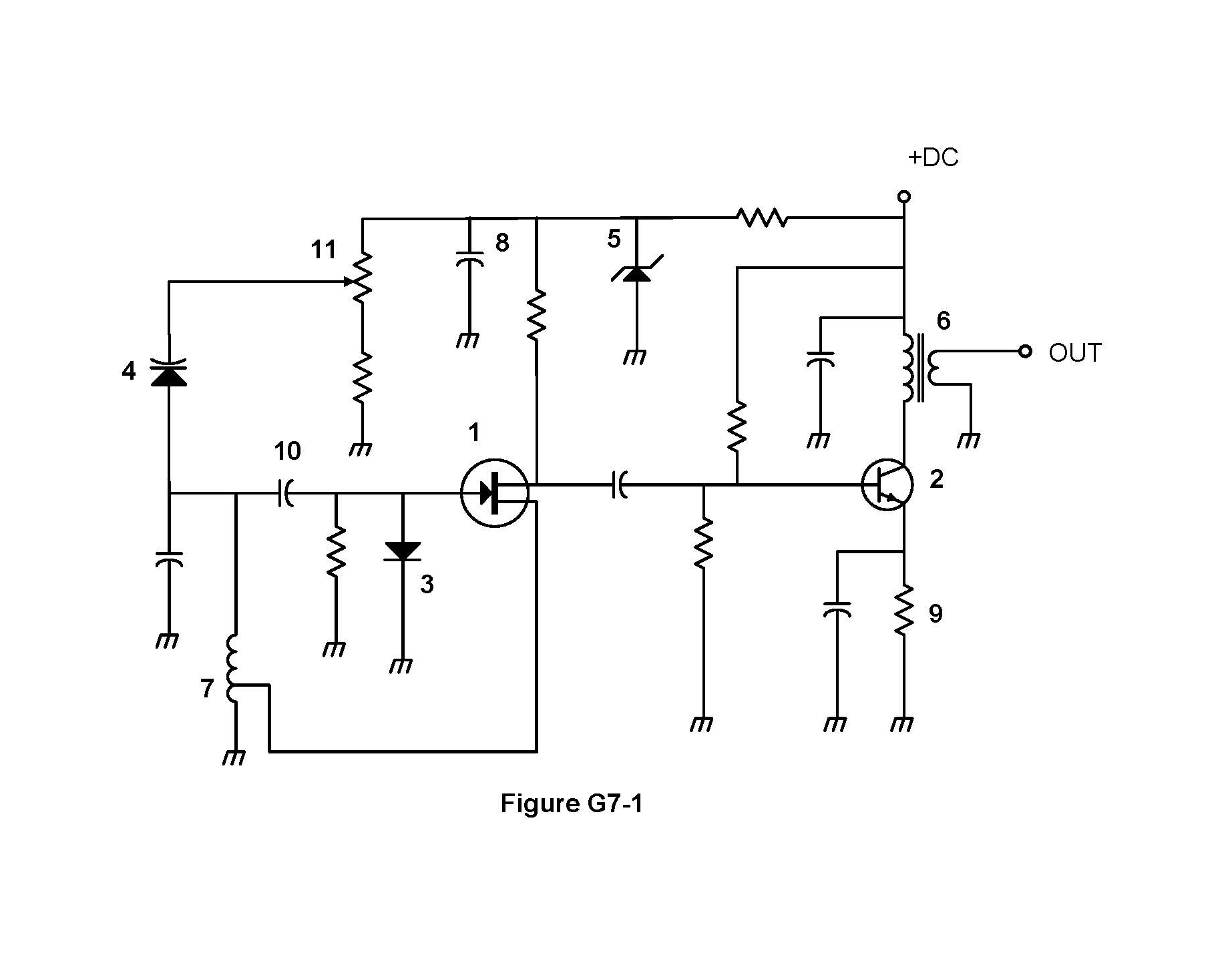
- Symbol 7 (correct answer)
- Symbol 11
- Symbol 6
- Symbol 1
Correct answer: A, Symbol 7
Explanation
An inductor is drawn as a series of loops. A tapped inductor has an extra lead connected partway along the winding, which divides the coil into two sections. Symbol 7 shows one coil going to ground with a tap that leads to the JFET's source. A tapped coil like this supplies feedback in a Hartley oscillator.
Why the other answers are wrong
- B, Symbol 11: Symbol 11 has an adjustable tap, but it is a zigzag resistor with a wiper (a potentiometer), not a coil.
- C, Symbol 6: Symbol 6 has two separate windings coupled through a solid core, so it is a transformer, not a single tapped inductor.
- D, Symbol 1: Symbol 1 is an N-channel JFET with gate, source and drain. It has no winding.