Technician Question T6C06
T6C: Circuit diagrams: use of schematics, basic structure; Schematic symbols of basic components
What is component 6 in figure T-2?
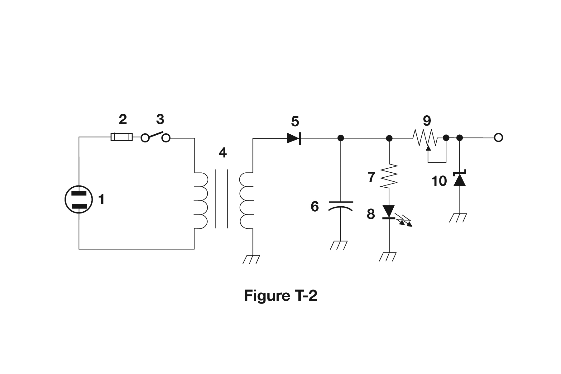
- Resistor
- Capacitor (correct answer)
- Regulator IC
- Transistor
Correct answer: B, Capacitor
Explanation
Component 6 is a capacitor: two parallel plates separated by a gap, with no conducting path straight through. US schematics usually draw any fixed capacitor with one straight plate and one curved plate. A polarized type would also carry a "+" sign, and this one has none. It runs from the output of diode 5 to ground, so it acts as a filter: it charges on the peaks and smooths the pulsing DC.
Why the other answers are wrong
- A, Resistor: Resistors are drawn as zigzag lines, like components 7 and 9. Component 6 is two separated plates instead.
- C, Regulator IC: A regulator IC is drawn as a rectangle with labeled pins (input, output, ground), and this figure has none.
- D, Transistor: A transistor shows a base bar with collector and emitter leads, usually inside a circle, as in figure T-1. It has no parallel plates.