Element 8 Question 8-10A6
C8A10: Circuits-2
You are troubleshooting a component on a printed circuit board in a RADAR system while referencing the Truth Table in Fig. 8A8. What kind of integrated circuit is the component?
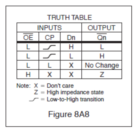
- D-type Flip-Flop, 3-State, Inverting. (correct answer)
- Q-type Flip-Flop, Non-Inverting.
- Q-type Directional Shift Register, Dual.
- D to Q Convertor, 2-State.
Correct answer: A, D-type Flip-Flop, 3-State, Inverting.
Explanation
The table shows a data input (Dn) that is captured on the low-to-high clock edge, with no change while the clock is low. That is a D-type, edge-triggered flip-flop. The output is Q-bar: D = H gives L and D = L gives H, so it inverts. When output enable (OE-bar) is high, the output goes to Z (high impedance), a third state besides H and L. So it is a 3-state, inverting D flip-flop.
Why the other answers are wrong
- B, Q-type Flip-Flop, Non-Inverting.: There is no 'Q-type' flip-flop; Q is the name of an output. The table also shows the output is inverted (D = H gives L), so it is not non-inverting.
- C, Q-type Directional Shift Register, Dual.: A shift register passes data from stage to stage. This table shows a single clocked latch per bit, and 'Q-type' is not a real device family.
- D, D to Q Convertor, 2-State.: There is no 'D to Q convertor'. The Z row shows a high-impedance third state, so the output is 3-state, not 2-state.