Element 8 Question 8-26C3
C8C26: Power Supplies
The circuit shown in Fig. 8C10 is the output of a switching power supply. Measuring from the junction of CR6, CR7 and L1 to ground with an oscilloscope, what waveform would you expect to see?
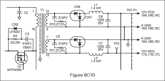
- Filtered DC.
- Pulsating DC at line frequency.
- AC at line frequency.
- Pulsating DC much higher than line frequency. (correct answer)
Correct answer: D, Pulsating DC much higher than line frequency.
Explanation
In Fig. 8C10, the transformer T1 is driven by MOSFET Q1 switching at tens of kHz or more, not at the power-line frequency. CR6 rectifies the secondary pulses, and CR7 is the freewheeling (catch) diode that clamps the junction near ground when Q1 is off. Before L1 and C6 smooth it, the junction shows rectangular pulsating DC at the switching rate. You only see filtered DC after the LC filter.
Why the other answers are wrong
- A, Filtered DC.: Filtered DC appears only after L1 and C6 have smoothed the pulses, at the 12 V output, not at the diode junction before the choke.
- B, Pulsating DC at line frequency.: This is a switch-mode supply. The transformer runs at Q1's switching frequency, so the rectified pulses are far above 60 Hz.
- C, AC at line frequency.: The diodes have already rectified the waveform at that point, and its frequency is set by the switching transistor, not by the line.