Amateur Extra Question E5C10
E5C: Coordinate systems and phasors in electronics: rectangular coordinates; polar coordinates; phasors; logarithmic axes
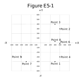
Which point on Figure E5-1 best represents the impedance of a series circuit consisting of a 400-ohm resistor and a 38-picofarad capacitor at 14 MHz?
- Point 2
- Point 4 (correct answer)
- Point 5
- Point 6
Correct answer: B, Point 4
Explanation
A series RC circuit has Z = R - jXC. XC = 1/(2πfC) = 1/(2π x 14 x 10^6 Hz x 38 x 10^-12 F) ≈ 299 Ω, so Z ≈ 400 - j300 Ω. In Figure E5-1, resistance is plotted on the X axis and reactance on the Y axis. Capacitive (negative) reactance goes below the X axis, so the point at X = +400, Y = -300 is Point 4.
Why the other answers are wrong
- A, Point 2: Point 2 is at 400 + j300, which is inductive reactance. A capacitor's reactance is negative, so the point belongs below the resistance axis.
- C, Point 5: Point 5 is at -400 - j300. A real resistor never has negative resistance, so a series RC impedance can't be left of the Y axis.
- D, Point 6: Point 6 sits at about 400 Ω on the resistance axis, which treats the circuit as purely resistive and ignores the capacitor's roughly 300 Ω of reactance.