Amateur Extra Question E7B10
E7B: Amplifiers: class of operation; vacuum tube and solid-state circuits; distortion and intermodulation; spurious and parasitic suppression; switching-type amplifiers
In Figure E7-1, what is the purpose of R1 and R2?
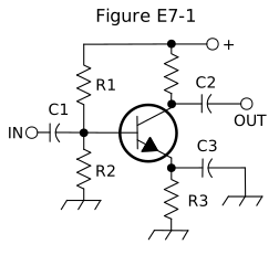
- Load resistors
- Voltage divider bias (correct answer)
- Self bias
- Feedback
Correct answer: B, Voltage divider bias
Explanation
R1 runs from the positive supply to the base, and R2 runs from the base to ground. Together they form a voltage divider that holds the base at a steady DC voltage, which sets the transistor's operating point. This divider bias makes the operating point fairly independent of the transistor's gain. Input coupling capacitor C1 keeps the input source from upsetting that DC voltage.
Why the other answers are wrong
- A, Load resistors: The collector load resistor is the separate resistor between the supply and the collector, where the output is taken; R1 and R2 connect only to the base.
- C, Self bias: Self bias in this circuit comes from emitter resistor R3, whose voltage drop sets the bias; R1 and R2 set a fixed base voltage from the supply.
- D, Feedback: A feedback resistor would connect from the output (collector) back to the input; R1 comes from the supply and R2 goes to ground, so neither carries output signal back.