Amateur Extra Question E7D06
E7D: Power supplies and voltage regulators; solar array charge controllers
What is the purpose of Q1 in the circuit shown in Figure E7-2?
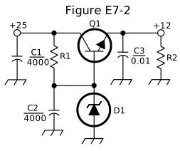
- It provides negative feedback to improve regulation
- It provides a constant load for the voltage source
- It controls the current to keep the output voltage constant (correct answer)
- It provides regulation by switching or “chopping” the input DC voltage
Correct answer: C, It controls the current to keep the output voltage constant
Explanation
Q1 is the series pass transistor. Zener diode D1 holds Q1's base at a fixed voltage, so the emitter output stays about 0.6 V below that voltage. If the input rises or the load changes, Q1 conducts more or less current. It drops the extra voltage across itself and keeps the +12 V output steady. Q1 works in its linear region, not as a switch.
Why the other answers are wrong
- A, It provides negative feedback to improve regulation: This simple circuit has no error amplifier feeding output changes back; Q1 follows the zener's fixed voltage like an emitter follower.
- B, It provides a constant load for the voltage source: Q1 passes whatever current the load needs; R2 is the constant load (bleeder) on the output, not Q1.
- D, It provides regulation by switching or “chopping” the input DC voltage: Switching or chopping is how a switching regulator works; Q1 conducts continuously in its linear region and turns the extra voltage into heat.