Amateur Extra Question E7D07
E7D: Power supplies and voltage regulators; solar array charge controllers
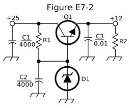
What is the purpose of C2 in the circuit shown in Figure E7-2?
- It bypasses rectifier output ripple around D1 (correct answer)
- It is a brute force filter for the output
- To prevent self-oscillation
- To provide fixed DC bias for Q1
Correct answer: A, It bypasses rectifier output ripple around D1
Explanation
C2 is a large 4000 µF capacitor connected in parallel with Zener diode D1 at Q1's base. R1 feeds that point from the rectified +25 V supply, so some ripple gets through. C2 shunts that ripple to ground around D1, giving a clean reference voltage at the base. Because the output follows the base, a clean reference means a clean output.
Why the other answers are wrong
- B, It is a brute force filter for the output: The brute-force input filter is C1 across the +25 V line, and C3 handles the output; C2 sits only at the base reference.
- C, To prevent self-oscillation: Small capacitors near a pass transistor can help prevent oscillation, but C2 is a 4000 µF filter across the Zener reference, meant to remove ripple.
- D, To provide fixed DC bias for Q1: The DC bias for Q1 comes from Zener diode D1 fed through R1; C2 only filters AC ripple from that voltage.