Amateur Extra Question E7D08
E7D: Power supplies and voltage regulators; solar array charge controllers
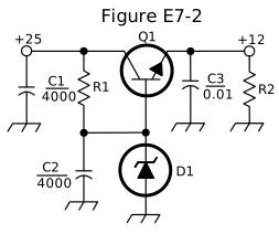
What type of circuit is shown in Figure E7-2?
- Switching voltage regulator
- Common emitter amplifier
- Linear voltage regulator (correct answer)
- Common base amplifier
Correct answer: C, Linear voltage regulator
Explanation
Figure E7-2 takes an unregulated +25 V input and produces a steady +12 V output. Zener diode D1 sets the reference voltage at the base of series pass transistor Q1. Q1 conducts continuously and drops the extra voltage as heat. A regulator whose control element works in its linear region this way is a linear voltage regulator. The filter capacitors and bleeder resistor R2 complete the supply.
Why the other answers are wrong
- A, Switching voltage regulator: A switching regulator rapidly turns its pass device fully on and off and needs an inductor or transformer to store energy; this circuit has neither.
- B, Common emitter amplifier: Q1 has a common collector (emitter follower) connection, and the circuit carries no signal to amplify; it delivers a regulated DC voltage.
- D, Common base amplifier: Nothing here has a grounded base with signal into the emitter; the transistor works as a DC pass element in a power supply.