Technician Question T6C02
T6C: Circuit diagrams: use of schematics, basic structure; Schematic symbols of basic components
What is component 1 in figure T-1?
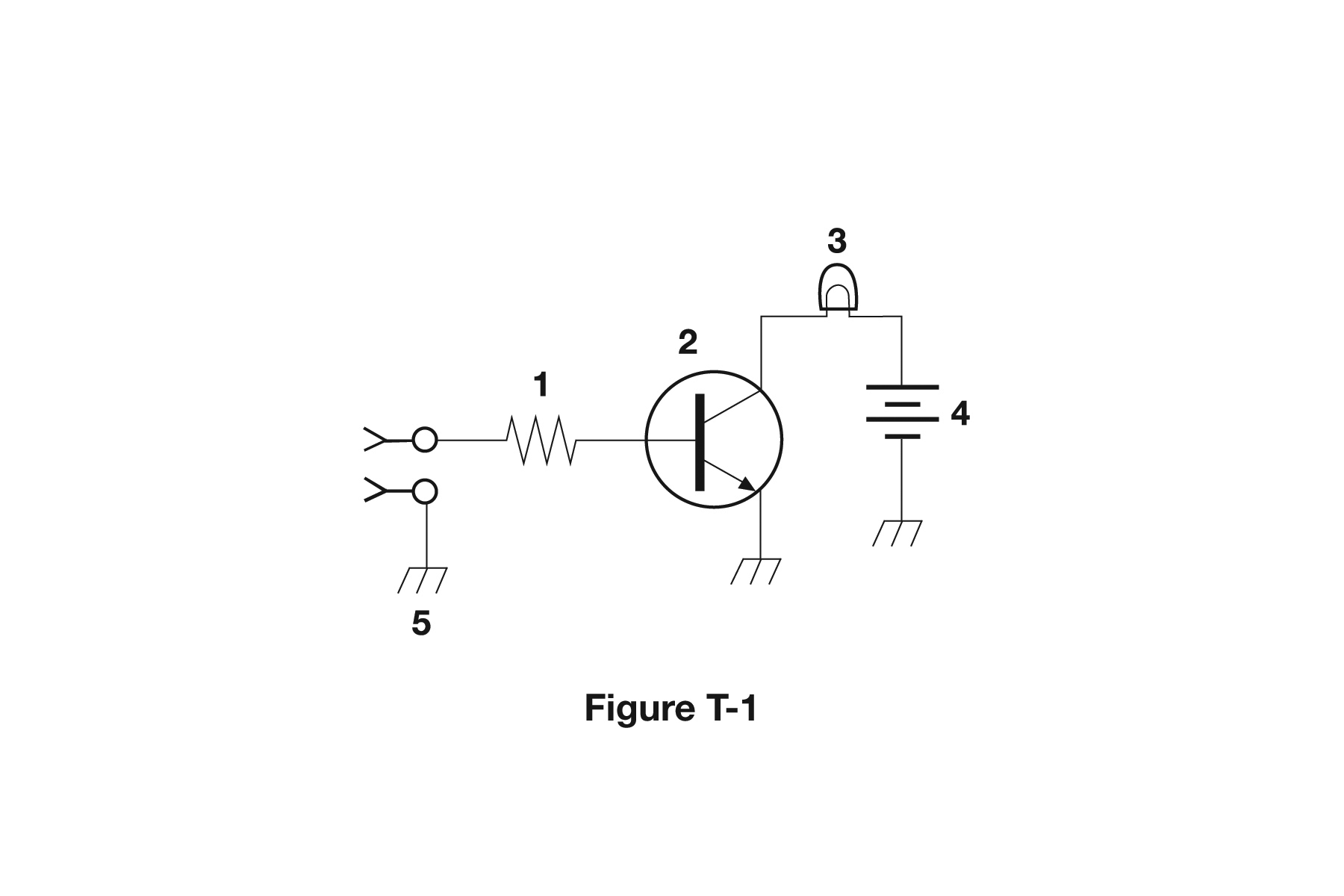
- Resistor (correct answer)
- Transistor
- Battery
- Connector
Correct answer: A, Resistor
Explanation
Component 1 is drawn as a zigzag line, the standard schematic symbol for a fixed resistor. In Figure T-1 it sits between the input connector and the transistor's base and limits the current flowing into the base. Any zigzag between two leads means resistance, whatever its value.
Why the other answers are wrong
- B, Transistor: The transistor is component 2, the circle with a base bar and an emitter arrow. It is not the zigzag line.
- C, Battery: A battery is drawn as alternating long and short parallel lines, like component 4, not as a zigzag.
- D, Connector: The connectors are the open circles with forked tips at the left input. The zigzag is a resistor wired after them.