Technician Question T6C03
T6C: Circuit diagrams: use of schematics, basic structure; Schematic symbols of basic components
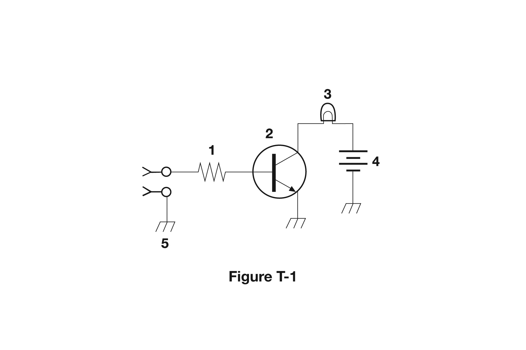
What is component 2 in figure T-1?
- Resistor
- Transistor (correct answer)
- Indicator lamp
- Connector
Correct answer: B, Transistor
Explanation
Component 2 is a bipolar junction transistor. It is drawn as a circle around a thick bar (the base), with two angled leads (the collector and the emitter). The arrow on the emitter points outward, which makes it an NPN type. A small base current fed through resistor 1 switches the larger collector current that lights lamp 3.
Why the other answers are wrong
- A, Resistor: A resistor is drawn as a zigzag line, like component 1 in the same figure. It has no circle, bar or emitter arrow.
- C, Indicator lamp: The indicator lamp is component 3: a rounded bulb outline with a filament loop inside, wired between the collector and the battery.
- D, Connector: The connector is component 5, shown at the input as open circles with V-shaped contacts. It is not the circled bar-and-arrow symbol.