Technician Question T6C09
T6C: Circuit diagrams: use of schematics, basic structure; Schematic symbols of basic components
What is component 4 in figure T-2?
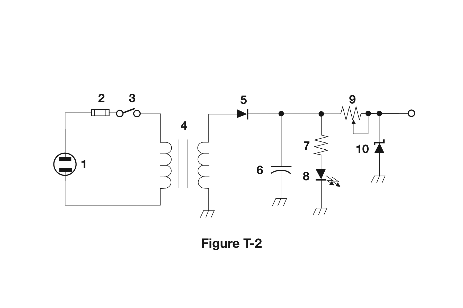
- Variable inductor
- Double-pole switch
- Potentiometer
- Transformer (correct answer)
Correct answer: D, Transformer
Explanation
Component 4 is a transformer. It shows two coils, the primary and secondary windings, on either side of parallel lines that stand for an iron core coupling them magnetically. It changes the AC from source 1 to a different voltage before diode 5 rectifies it.
Why the other answers are wrong
- A, Variable inductor: A variable inductor is a single coil with an arrow or adjustable tap. Component 4 has two separate windings coupled by a core.
- B, Double-pole switch: A double-pole switch shows two linked blades with their contacts. The only switch here is component 3, which is single-pole.
- C, Potentiometer: A potentiometer is a zigzag resistor with an arrow wiper, like component 9. It is not two coils around a core.