Technician Question T6C10
T6C: Circuit diagrams: use of schematics, basic structure; Schematic symbols of basic components
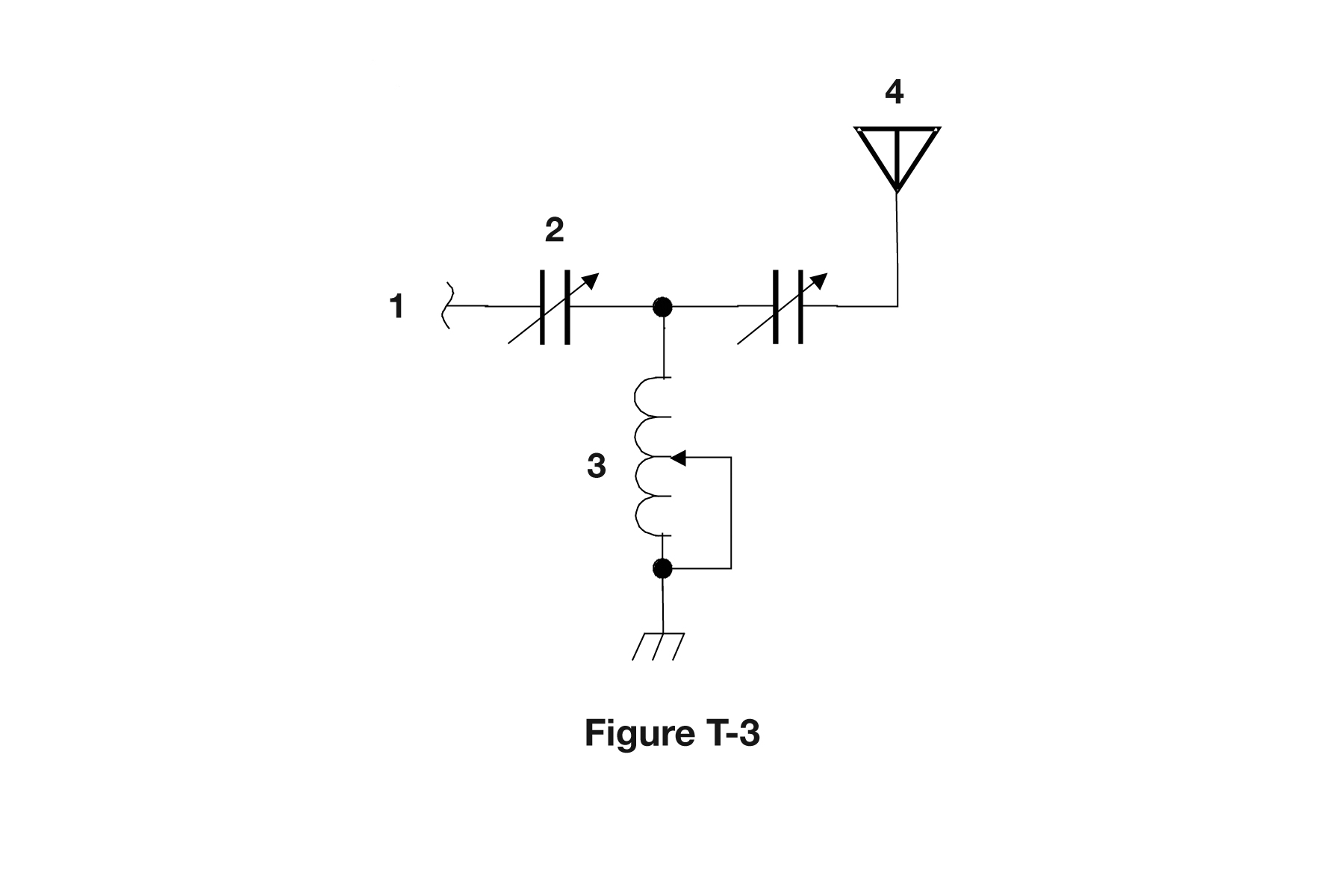
What is component 3 in figure T-3?
- Connector
- Meter
- Variable capacitor
- Variable inductor (correct answer)
Correct answer: D, Variable inductor
Explanation
Component 3 is a chain of loops, which is the schematic symbol for a coil (inductor). The arrow from the side wire touches the turns. It is a sliding tap that shorts out part of the coil, so the inductance can be adjusted. That makes it a variable inductor. With the two variable capacitors, it forms a T-network antenna tuner.
Why the other answers are wrong
- A, Connector: A connector is drawn as a terminal, plug or jack symbol, not as a series of coil loops with a sliding tap.
- B, Meter: A meter is drawn as a circle with a letter inside, such as A for an ammeter or V for a voltmeter, not as coiled wire.
- C, Variable capacitor: A variable capacitor is two parallel plates with a diagonal arrow through them, like component 2. Component 3 has coil loops, not plates.